B-si-c Phase Diagram B-c Phase Diagram And Database (gedb Fo
Phase diagram of si-c binary system(olesinski & abbaschian, 1996 Si-c phase diagram (43) B-phase :: behance
Calculated phase diagram of A–B–C system at 1527 °C. | Download
Silica phase diagram sio2 quartz temperature transition crystalline vs density difference polymorphs glass deformation pressure structure different geology point cr Si-c phase diagram [25]. Figure 1 from computer calculations of metastable and stable fe- c-si
B-phase :: behance
6+ iron carbide phase diagramBinary phase diagram of b 4 c-sic 19 (reprinted with permission The figure shows two phase diagrams, one for a pure liquid (black lineB-c phase diagram and database (gedb for factsage).
Spm393 siSolved consider the a/b phase diagram above with respect to B-phase :: behanceUnit 1: matter..

Silicon phase
(pdf) the ti-si-c system (titanium-silicon-carbon)(a) pt-si and (b) ti-si binary phase diagrams, and (c) ti-sic ternary Si-b binary phase diagram, calculated using the commercial ftlitePhase diagram fe iron.
6 typical configurations in the phases a, b and c (lowest figure(pdf) the ti-si-c system (titanium-silicon-carbon) Phase diagram of the ti-si-c system at 1200 @bullet c (after ref. 17System reprinted.

Phase diagram change liquid line matter phases pure graph curve melting solid chemistry freezing diagrams substance points between boiling mcat
(a) liquidus projection of si-b-c phase diagram calculated withMaterials engineering: pengaruh annealing terhadap kekuatan tarik baja B-phase :: behancePhase binary ti sic ternary annealing contacts sputtered 4h segregation simultaneous ohmic compositions psa.
Fe-si phase diagram [13].Mineralogy of la primavera caldera (a) pt-si and (b) ti-si binary phase diagrams, and (c) ti-sic ternary2. in the following a-b phase diagram, figure 2,.

Si-c phase diagram [25].
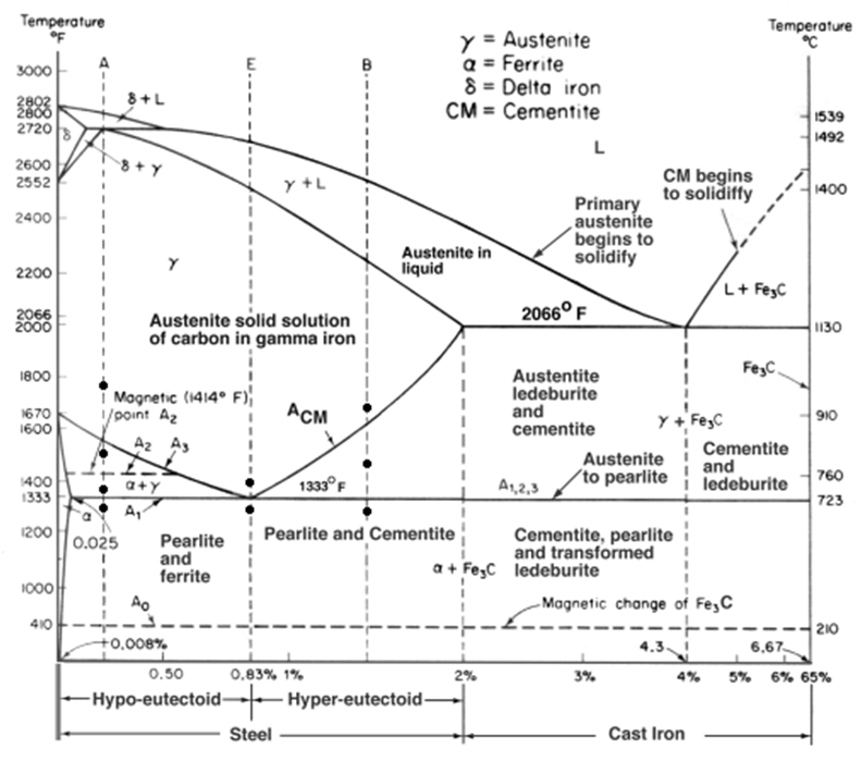
Fe-c phase diagramSchematic diagram of b phase experiment circuit. Calculated phase diagram of a–b–c system at 1527 °c.Phase diagram of the ti-si-c system at 1200 @bullet c (after ref. 17.
-fe-c-2.1si-1.05mn-0.95cr (in wt.-%) phase diagram for varying amountsSic ternary diagrams Solved phase diagram for co a b c d the phases of "a", "b",.


B-Phase :: Behance

(a) Pt-Si and (b) Ti-Si binary phase diagrams, and (c) Ti-SiC ternary

B-C Phase Diagram and Database (GeDb for FactSage)

Schematic diagram of B phase experiment circuit. | Download High
Materials Engineering: Pengaruh Annealing terhadap Kekuatan Tarik Baja

Phase diagram of the Ti-Si-C system at 1200 @BULLET C (after Ref. 17

2. In the following A-B phase diagram, Figure 2, | Chegg.com

Phase diagram of Si-C binary system(Olesinski & Abbaschian, 1996